Odour Presentation System
AKA: Odour Delivery Manifold
AKA: Odour Delivery Device
AKA: ODD
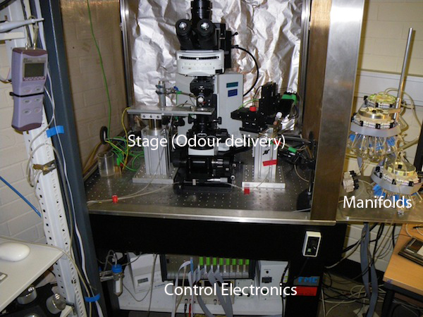
This system was developed in order synchronise odour selection and presentation with patch recordings (on patch rigs) or optical recordings (two-photon microscope). Basically, it consists of polymer manifolds, control electronics, and control software. The polymer manifolds can each hold up to eight screw-cap erlenmeyer flasks (eight odours) and the control box can handle up to eight of these manifolds, allowing for up to sixty-four independent odour channels, though normally one ore more channel(s) is/are left blank as controls/backgrounds.
Polymer Manifolds
The manifolds are machined either from polyether ether ketone (PEEK) or polytetrafluoroethylene (PTFE). Because of variety in the chemical properties of the odours, no single polymer was suitable. Peek was chosen for most of the manifolds because of its inertness, strength, and resistance to adhesion. The softer, more delicate PTFE manifolds should only be used for molecules that might attack PEEK. See here for a list of chemicals and their compatibility with PEEK. Here is a spreadsheet showing the results of pressure tests.
The odour channels were drilled out of solid polymer blocks, and the flow controlled by Lee LHDA1221515H solenoid valves. The following diagram illustrates the flow patterns through the manifolds:


Flasks
Flasks are 25 ml screw thread erlenmeyer type conical flasks. They were bought from Witeg in Germany (Article Number 5 507 001) for about 13 euros each. Witeg appear to have bought them from a Czech company (likely Vitrum, now part of VWR). The part number for that company was 632 411 199 025.
| Screw thread | Flask O.D. | Height/mm |
|---|---|---|
| GL18 (or DIN168) | 42 | 70 |
Control electronics
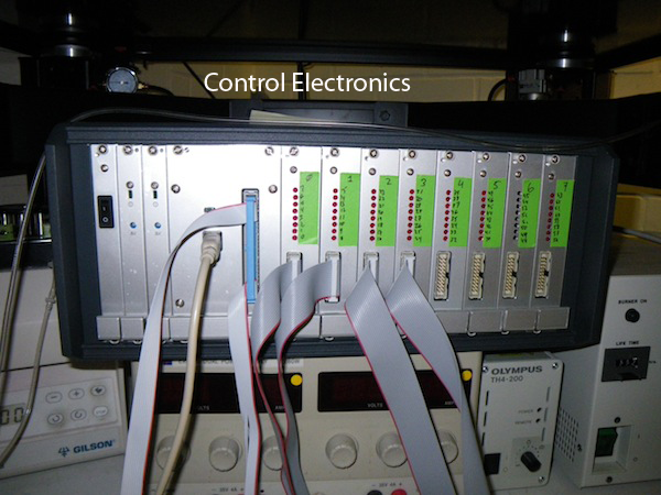
The control 'box' consists of two power supplies (5V for the digital circuitry and 12V for the solenoid drivers), an ACCES USB-DIO-96-OEM digital I/O card, and eight very simple PCBs, each of which drives the solenoid valves of a single manifold. The PCBs contain simple transistor circiuts and use the DIO lines to control the solenoid valves. At this time, each output channel from the PCBs simultaneously operates BOTH solenoid valves on the corresponding manifold channel. This will be changed in the next version of the PCBs in order to allow independent operation of each solenoid valve. This, we discovered, will be useful for testing and depressurising the odour vials.
One of the card's 24-way sockets has been extended to the front panel of the control box and made available as GPIO. This is useful for things like triggering and monitoring when the transistors (DIO lines) change state. An additional 8-bit socket has been left open on the back plane. Most likely these pins will be used to add the independent solenoid operation on the next round of PCBs (not enough bits? Might need to map some from the front panel socket).
The 96 channels are arranged as four groups of 24 channels (visible on the DIO card), each comprising 3 'bytes', referred to as 'ports' of data lines. As it is configured, ports 0 to 7 operate PCBs (and therefore manifolds) 0-7, port 8 is left open on the back plane inside the control box, and ports 9 - 11 are available on the front panel. During initialisation, the control software sets ports 0-7, 8, 9 for output and ports 10, 11 for input. Currently, pin one on port 9 switches to HIGH for the duration of ANY odour presentation. Its value is recorded along with electrophysiological recordings in order to identify the stimulation events in the data. Any change on port 11 acts as a trigger for the control software. Port 10 is currently unused, but may be needed in upgrading the PCBs.
Wiring up the ODD box
- The front panel requires a USB input from the computer
- There is a 50 pin IDC connector next to this to which you must connect the TTL trigger out from the ITC and from which you can record a valve open signal
- the TTL trigger comes in at the top of this IDC connector
- the valve open acknowledgement signal comes out on pin 1 of port 9 of the USB DIO card(see above) which is the second pin up from the bottom right on this connector.
- Ground pins are located on the left (looking at the IDC on the ODD box)
- There are 8 x 20 way IDC connectors each of which can control 8 valve pairs.
- the lowest 8 pairs of pins are the digital out signals
- each pair of pins consists of an IO output and a ground (the orientation doesn't matter for the solenoids)
- the lowest pair ⇒ channel 7
- the highest of the 8 pairs (3rd pair down from the top of the connector) ⇒ channel 0
- the red wire in the cable should be at the bottom of the IDC connector (see picture below)
- note that the LED indicators count up from 0 to 7 while the IDC connectors count down from 0 to 7!
| L | R |
|---|---|
| * | * |
| * | * |
| G | 0 |
| G | 1 |
| G | 2 |
| G | 3 |
| G | 4 |
| G | 5 |
| G | 6 |
| G | 7 |
Diagram of one of the eight 20 way IDC connectors on the ODD itself, notch would be on the right.
Wiring up the Sputniks
- the pair of wires with the red core should connect to the highest numbered valve pair on any sputnik
- connect each wire pair further into the ribbon cable to the next lower numbered valve pair
- the 10 way IDC connectors only expose have 4 connections for the 2 pairs of pins on the pair of valves for each channel
- make sure you connect the live sockets to the valves
- if unsure run a valve testing protocol and listen!
- Jonny has a ValveTest32 nclamp protocol and corresponding ValveTest32.odd config file which scans all 32 valves!
Blue Prints
Howard from Electronics has kindly provided the blue prints for the control box.


